
On a regular basis I am asked to explain something pertaining to live-tool machining on a lathe, or "mill-turn," as it is commonly referred to in the industry. Even people with a CNC turning background are sometimes a little confused, especially in the areas of tooling and when the use of an additional Y-axis is necessary.
In this article, I will shine some light on the basics of live-tool machining and the application of the optional Y-axis.
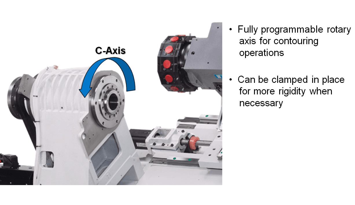
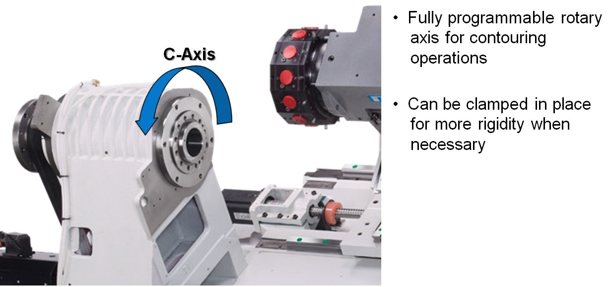
Mill-turn machines can vary from the simpler 3-axis lathes (X, Z & C), where the spindle becomes a separate axis that is controllable angularly for milling operations, to the more advanced 6-axis machines with the addition of a linear Y-axis, W-axis and a secondary programmable sub-spindle or counter-spindle. On machines with a secondary spindle, the W-axis is used to position the secondary spindle for machining.
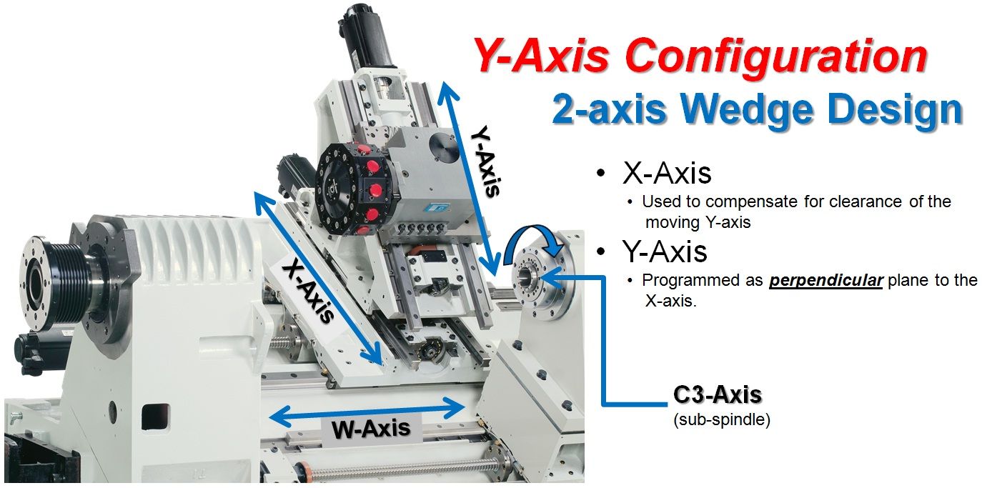
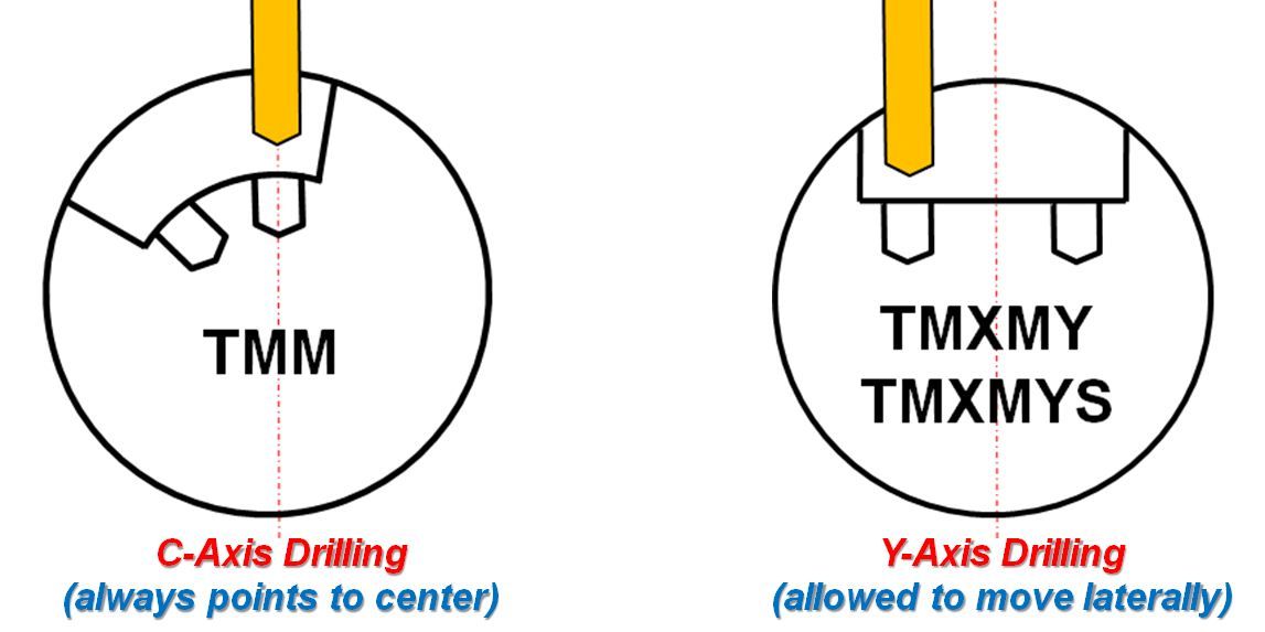
In the image above, you will notice that the Y-axis is actually installed using a narrowly angled “wedge” design, but even on machines with this type of configuration, the Y-axis always moves in a perpendicular motion to the X-axis.
A common mystery surrounding mill-turn technology is knowing when a Y-axis is necessary and when a particular feature can be machined on a simpler 3-axis machine with only the C-axis. Basically, a Y-axis is only necessary when the tool must be pulled off of the centerline of the part. Even then, most often it is only necessary for features being machined into the circumference of the part. Features on the face of the part can usually be completed with only the use of the C-axis in most cases.
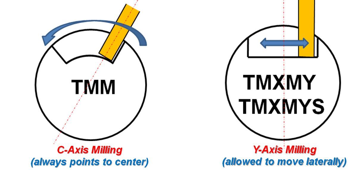
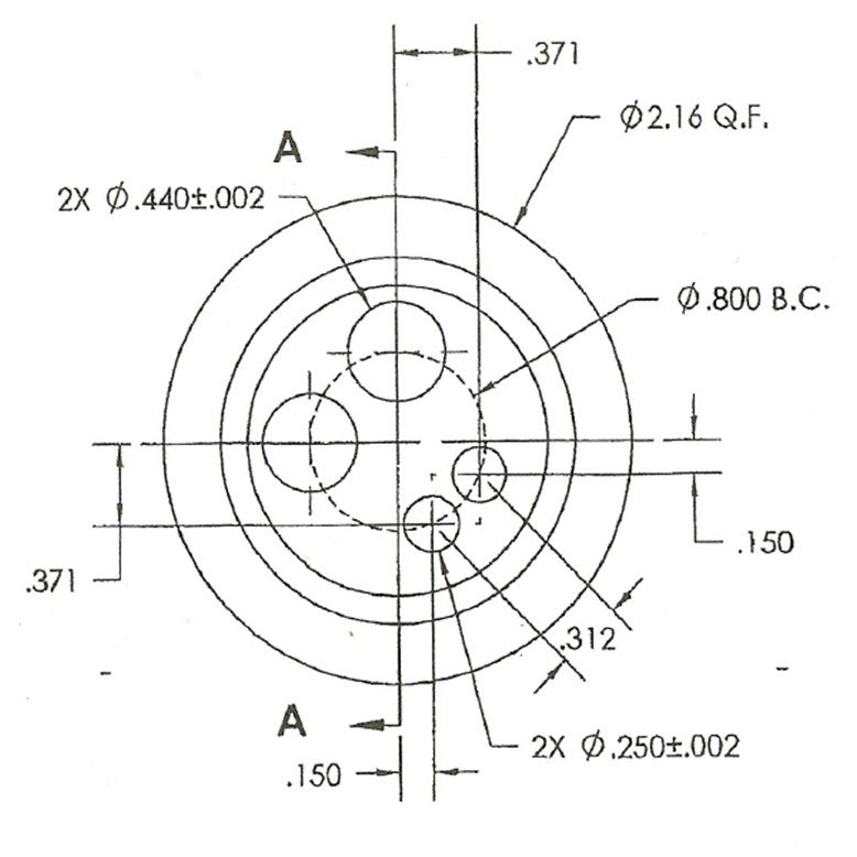
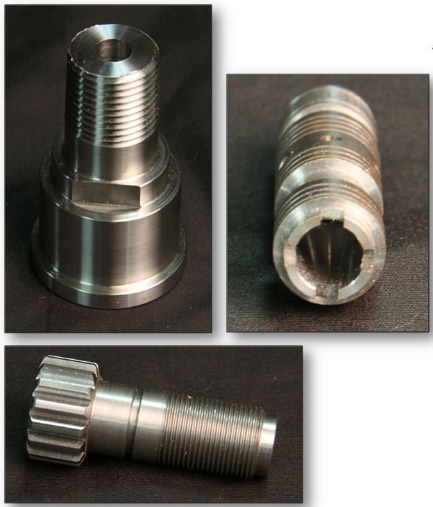
The parts pictured below are good examples of features that can be created with just the addition of the C-axis. Even with the holes depicted in the blueprint that are not on the centerline of the part, the C-axis can position to allow the X-axis to move into position and machine the feature.
The parts pictured below have features that would require a Y-axis. Again, the Y-axis is a perpendicular axis to the X-axis and can be used to move the tool up or down, above or below center. The flats on the brass part could technically be machined with just the C-axis, but because of their location in the middle of the part, a Y-axis would be better suited for this feature. However, the rounded edges of the yoke on the end of the part would definitely need the Y-axis to profile the feature. On the second part, the flats would need to be milled with the part oriented as shown in the top picture. You can easily see that the tool would need to be raised above center to cut this particular profile.
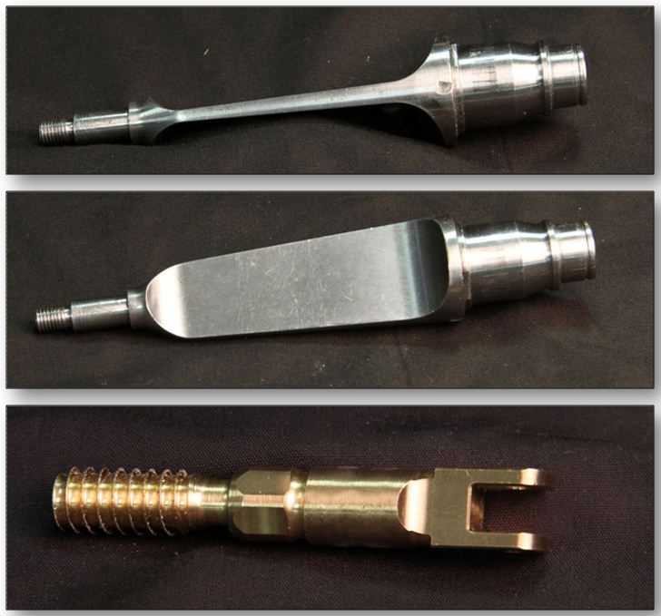
This video shows how the use of a Y-axis can be helpful in machining flats. Although the tool in the video is oriented along the Z-axis, the concept would be the same if the tool was in a perpendicular orientation to the part, which would be useful on the brass part pictured above.
Find more helpful resources, such as training videos and webinars here.
Find Resources